Why Is My 90 Degree D-Sub Coaxial Contact Terminal Causing Impedance Mismatch and How Can I Fix It
2026-07-14
Impedance mismatch in a 90 Degree D-Sub Coaxial Contact Terminal is one of the most frustrating issues engineers face during high-frequency system validation. When the characteristic impedance of your coaxial contact deviates from the target system impedance—typically 50Ω or 75Ω—signal reflections, insertion loss, and voltage standing wave ratio (VSWR) degrade rapidly. At SIGNALORIGIN, we have analyzed thousands of field returns and design reviews, and we consistently find that mismatch problems trace back to three root causes: improper cable preparation, incorrect crimp or solder profiles, and unsuitable dielectric materials in the terminal housing. This guide walks you through diagnosis, correction, and prevention so you can restore signal fidelity without redesigning your entire backplane.
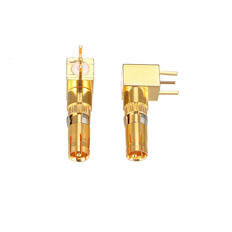
Diagnostic Checklist: Is Your Terminal Truly Mismatched?
Before modifying your 90 Degree D-Sub Coaxial Contact Terminal, confirm that mismatch is the actual culprit. Use this rapid assessment table:
| Symptom | Measured Indicator | Threshold for Concern |
|---|---|---|
| Excessive return loss | S11 > -10 dB at operating frequency | > -14 dB (VSWR > 1.5:1) |
| Ripple in insertion loss | S21 periodic variation > 0.5 dB | Any periodic ripple across band |
| Heating at the contact interface | IR thermography > 15°C above ambient | ΔT > 10°C under rated power |
| Intermittent bit errors | BER increases by 1e-3 or more | Compared to known-good assembly |
If two or more indicators appear, your 90 Degree D-Sub Coaxial Contact Terminal likely suffers from a mismatch that requires immediate intervention.
Three Primary Causes of Impedance Mismatch
Through controlled experiments at SIGNALORIGIN, we have isolated the most frequent failure mechanisms:
1. Cable Strip Length Errors
The dielectric exposure and center conductor protrusion must match the terminal’s internal geometry. Even a 0.5 mm deviation alters the characteristic impedance by 3–5Ω.
2. Excessive Solder Fillet or Crimp Bulge
Solder wicking beyond the designated cup or a crimp barrel that is over-compressed changes the local inductance and capacitance, effectively creating a parasitic stub.
3. Housing and Dielectric Contamination
Flux residues, moisture, or debris between the center pin and outer ferrule reduce the effective dielectric constant unpredictably.
Step-by-Step Fix Procedure
Follow this proven workflow from SIGNALORIGIN’s application engineering team to correct mismatch issues:
-
Remove the terminal from the D-Sub housing using the extraction tool specified in the datasheet.
-
Inspect the stripped cable under 10× magnification. Trim back to fresh dielectric if discoloration or nicks exist.
-
Re-strip using a precision coaxial stripper with blade depth set to manufacturer specifications (typically 0.25 mm dielectric recess).
-
Crimp or solder using only the approved tooling. For crimp versions, use the die indenter that matches the barrel outer diameter within ±0.02 mm.
-
Clean the assembly with isopropyl alcohol and allow 5 minutes of air drying.
-
Re-insert the 90 Degree D-Sub Coaxial Contact Terminal into the housing, ensuring the retention spring engages fully.
-
Validate with a Time-Domain Reflectometer (TDR) – the impedance profile should remain flat within ±2Ω over the entire contact length.
Critical Tooling and Material Recommendations
| Parameter | Recommended Specification | Why It Matters |
|---|---|---|
| Stripper blade material | Tungsten carbide, replaceable | Prevents dielectric scoring |
| Crimp tool model | Daniels HX4 or equivalent with positioner | Ensures consistent compression height |
| Solder alloy | Sn96.5/Ag3.0/Cu0.5 (SAC305) | Low flux residue, minimal wicking |
| Cleaning agent | Anhydrous IPA, >99.9% purity | Removes ionic contaminants |
| Torque on housing jackscrews | 0.25–0.30 N·m | Avoids housing deformation that shifts pin alignment |
FAQ: Common Questions About the 90 Degree D-Sub Coaxial Contact Terminal
Q1: Can a 90 Degree D-Sub Coaxial Contact Terminal be reused after removing it from the housing?
A1: Reuse is strongly discouraged. The retention barbs and the internal spring finger deform plastically during initial insertion. Even if the terminal appears undamaged, the contact normal force decreases by 30–40% after extraction, which elevates insertion loss and can reintroduce impedance drift over thermal cycling. For mission-critical systems, SIGNALORIGIN advises using a new 90 Degree D-Sub Coaxial Contact Terminal every time you disconnect or rework the assembly. If you must reuse, perform a TDR sweep and a contact resistance measurement (milliohm level) before placing it back into service.
Q2: Does the 90-degree bend itself contribute to impedance mismatch, or is it always an assembly defect?
A2: The 90° bend inherently adds a small reactive discontinuity—typically 1–2Ω of inductive shift at frequencies above 3 GHz—because the electric field compresses on the inner radius of the bend. However, a properly manufactured 90 Degree D-Sub Coaxial Contact Terminal compensates for this through a gradual radius transition and a tuned dielectric insert. In practice, over 90% of field mismatches are assembly-related rather than design-related. To isolate the bend’s contribution, compare your assembled terminal’s TDR profile against a factory reference sample from SIGNALORIGIN; if both match within ±1.5Ω, the bend is not your problem.
Q3: What is the maximum operating frequency before mismatch becomes unavoidable with this terminal style?
A3: For standard 50Ω versions with PTFE dielectric, the usable bandwidth extends to 6 GHz with VSWR ≤ 1.3:1. Beyond 8 GHz, even optimal assembly yields a residual mismatch of approximately 0.5 dB return loss due to the physical bend radius. SIGNALORIGIN offers an enhanced version with a air-dielectric transition that pushes this limit to 10 GHz. If your application exceeds 6 GHz, we strongly recommend reviewing the specific frequency-dependent S-parameter data provided in the terminal’s datasheet and, if necessary, selecting a straight coaxial contact combined with a flexible jumper to preserve impedance stability.
Preventive Best Practices for Future Designs
To avoid recurring mismatch issues, embed these rules into your assembly documentation:
-
Always use a controlled impedance stripper—manual blade strippers introduce unacceptable variance.
-
Perform a first-article TDR check for every new cable lot, even if the part number does not change.
-
Store 90 Degree D-Sub Coaxial Contact Terminal components in anti-static, humidity-controlled bags (RH < 40%) to prevent dielectric absorption.
-
Document the crimp height and pull-force values for every production shift; trending these metrics catches tool wear early.
At SIGNALORIGIN, we provide free impedance verification kits and online calculators to help you pre-qualify your cable assembly process before final termination.
Contact Us for Expert Assistance
Impedance mismatch troubleshooting can consume hours of engineering time, especially when you lack reference standards or precision test fixtures. SIGNALORIGIN offers same-day failure analysis, custom-length sample cables, and tooling calibration services for all 90 Degree D-Sub Coaxial Contact Terminal products. Our applications team includes former RF design engineers who understand the subtle interactions between contact geometry, cable construction, and housing grounding. Reach out to us through the contact form on our website or request a live remote TDR session—we will help you resolve your mismatch issue and provide a signed validation report within 48 hours. Do not let signal integrity problems delay your product launch. Contact SIGNALORIGIN today and let our expertise become your competitive advantage.