Why is Double Flanged Anchoring with Puddle Flange Ductile Iron Preferred Over Traditional Thrust Blocking Methods
2026-04-29
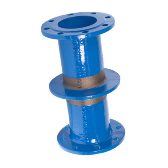
When engineers design restrained pipeline systems, the debate often centers on thrust restraint. Double Flanged Anchoring With Puddle Flange Ductile Iron has emerged as the superior solution, consistently outperforming bulky concrete thrust blocks. At FYL, we have witnessed this shift across waterworks and industrial projects, where reliability and space efficiency are non‑negotiable.
The Core Advantages Over Thrust Blocks
Traditional thrust blocks rely on passive soil resistance. They require large excavations, extended curing times, and are impossible to install in rocky or unstable ground. Double Flanged Anchoring With Puddle Flange Ductile Iron eliminates these challenges by creating an active mechanical lock between the pipe fittings and the surrounding soil or concrete structure.
| Feature | Traditional Thrust Block | Double Flanged Anchoring With Puddle Flange Ductile Iron (by FYL) |
|---|---|---|
| Installation time | 24‑48 hours curing | Immediate – no curing needed |
| Space required | Large excavation | Minimal trench width |
| Soil dependency | High – fails in loose/rocky soil | Low – works in any ground |
| Adjustability after install | None | Easy disassembly and repositioning |
| Corrosion resistance | Poor (concrete cracks) | Excellent (ductile iron + coatings) |
List of Operational Benefits
-
Zero Waiting Time – Backfill immediately after bolt tightening, shortening project schedules drastically.
-
Predictable Performance – Mechanical joint restraint provides calculated load capacity, unaffected by field variability of concrete.
-
Inspection Friendly – Bolts and flanges are visible and testable; thrust blocks hide potential failures.
-
Cost Saving – Reduces concrete material, formwork, labor, and later removal expenses.
Frequently Asked Questions (FAQ)
Q1: Can Double Flanged Anchoring With Puddle Flange Ductile Iron be used in all pipe diameters and pressure classes?
A1: Yes. Double Flanged Anchoring With Puddle Flange Ductile Iron is available from DN80 to DN2000 and pressure classes PN10 to PN40. The puddle flange is cast integrally with the ductile iron pipe or fitting, then double flanged ends provide bolted connections. FYL engineers can match any project specification. Unlike thrust blocks which require site‑mixed concrete with variable strength, this mechanical restraint offers a certified, repeatable thrust resistance per bolt torque, making it suitable for high‑pressure transmission mains and pumping stations.
Q2: How does installation in waterlogged or confined trenches compare between thrust blocks and double flanged anchoring?
A2: Thrust blocks cannot be poured underwater or in narrow trenches without dewatering and shoring, adding weeks of work. Double Flanged Anchoring With Puddle Flange Ductile Iron requires only a dry bolting zone, not a dry full excavation. The puddle flange anchors into the surrounding material (soil or concrete encasement) while the double flanged ends bolt directly to adjacent pipes. In confined spaces like valve chambers or inside tunnels, thrust blocks are often impossible; the double flanged puddle flange assembly from FYL fits precisely with no extra clearance.
Q3: What maintenance or replacement considerations apply years after installation?
A3: Traditional thrust blocks are permanent but problematic – when a valve or fitting needs replacement, the concrete must be jackhammered out, risking pipe damage and large disposal costs. Double Flanged Anchoring With Puddle Flange Ductile Iron allows full disassembly. Loosen the flange bolts, remove the spool or fitting, install a new component with the same flange drilling, and retorque. The puddle flange remains embedded, so only the bolted joint requires re‑engagement. FYL provides replacement gaskets and bolts for decades‑long service life without structural demolition.
Conclusion and Contact
Modern infrastructure demands verifiable, rapidly deployable, and maintainable thrust restraint. Double Flanged Anchoring With Puddle Flange Ductile Iron delivers exactly that, while thrust blocks remain a historical fallback for low‑consequence lines. FYL engineers this solution to meet AWWA C110, C111, and ISO 2531 standards, with full traceability.
Contact us today for project‑specific drawings, bolt torque calculations, or a site consultation. Let our team show you why leading contractors have switched to FYL for restrained joint systems that never wait for concrete to dry. Reach out through our website or call your regional FYL representative now.