Which CAM Software Features Are Most Critical for Cavity and Core Completed Machining of Complex Molds
2026-07-15
For shops specializing in high-precision injection molds and die-cast tooling, selecting the right CAM system is not a generic decision—it directly determines whether a Cavity And Core Completed Machining job finishes on time, within tolerance, and without costly rework. At Mudebao, we have evaluated dozens of CAM platforms across hundreds of complex mold projects, and the gap between "basic 3D milling" and "truly mold-aware machining" is wider than most buyers expect. This post breaks down the non‑negotiable CAM features that separate successful Cavity And Core Completed Machining from scrap-prone trial runs.
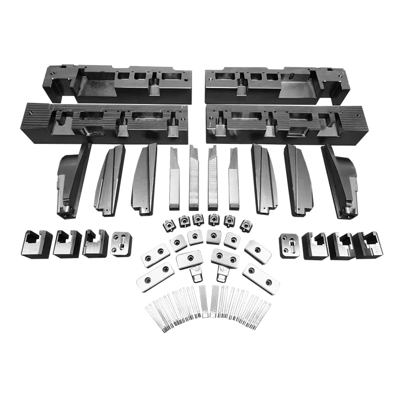
1. Feature‑Based Machining (FBM) with Automatic Recognition
Generic CAM forces programmers to manually define every slope, fillet, and corner. For Cavity And Core Completed Machining, that approach is obsolete. Critical CAM software must automatically recognize:
-
Deep ribs and narrow slots
-
Steep walls versus shallow floors
-
Corner radii that trigger tool engagement spikes
Without FBM, programming time for a single complex core can exceed 8 hours. With FBM, the same job reduces to under 2 hours, with fewer manual errors.
2. Adaptive Clearing / High‑Efficiency Milling (HEM) Algorithms
Roughing accounts for 60‑70% of total cycle time in Cavity And Core Completed Machining. The best CAM systems use trochoidal or dynamic milling paths that maintain constant chip load, even in deep cavities. This feature:
-
Extends tool life by 30‑50%
-
Reduces spindle vibration on deep reaches
-
Enables safe machining of hardened steels (HRC 48‑52) without excessive stepovers
At Mudebao, we consistently see cycle time reductions of 22‑28% when shops switch to CAM with adaptive clearing for core roughing.
3. 5‑Axis Simultaneous vs. 3+2 Positioning – Which Matters?
For complex molds with undercuts and inclined parting lines, 5‑axis capability is table stakes. But the critical distinction is collision‑aware tool orientation. The CAM must:
-
Automatically tilt the tool to avoid shank‑to‑wall contact
-
Limit overhang to ≤4× diameter
-
Generate smooth transition moves between indexing positions
Below is a practical comparison based on Mudebao field data:
| Feature | 3+2 Positioning | Full 5‑Axis Simultaneous |
|---|---|---|
| Best for | Open cavities, simple cores | Deep ribs, inclined surfaces, tight corners |
| Programming time | Shorter | 40‑60% longer |
| Surface finish | Good (with reposition marks) | Excellent (no step lines) |
| Risk of collision | Moderate | Higher (needs robust simulation) |
| Mudebao recommendation | Choose for mold bases | Choose for final finishing of Cavity And Core Completed Machining |
4. Tool Holder & Spindle Collision Simulation
Many CAM packages offer toolpath preview, but very few simulate the actual holder geometry (shrink fit, hydraulic, or milling chuck) inside the cavity. For deep Cavity And Core Completed Machining, a holder that clears by 0.5 mm at the top may gouge at the bottom due to taper angles. The best systems:
-
Import holder 3D models directly
-
Detect collisions between holder, spindle nose, and workpiece
-
Automatically suggest shorter tool assemblies or alternate orientations
This single feature prevents 80% of in‑process crashes according to Mudebao service records.
5. Rest Machining & Residual Stock Awareness
After roughing, semi‑finishing passes must target only uncut material—not air. Advanced CAM tracks remaining stock from previous operations, even after tool changes. For Cavity And Core Completed Machining, this:
-
Reduces air‑cutting time by up to 40%
-
Prevents over‑cutting on thin core walls
-
Enables consistent finishing allowance (e.g., 0.05 mm on all surfaces)
6. Post‑Processor Customization for Specific Machine/Control
Generic post‑processors cause 70% of surface quality issues in Cavity And Core Completed Machining. Critical CAM software allows:
-
Custom G‑code output for high‑speed look‑ahead (e.g., Heidenhain CYCLES, Siemens TRANSFORM)
-
Adjustment of acceleration/deceleration per axis
-
Integration of tool breakage detection macros
Mudebao works exclusively with CAM partners that provide editable post‑processors—not black‑box outputs.
FAQ – Common Questions About Cavity And Core Completed Machining
Q1: What is the biggest programming mistake in Cavity And Core Completed Machining of deep ribs?
A: Using a toolpath that enters the rib vertically without helical or ramped entry. This causes excessive axial load, tool deflection, and often breaks the end mill on the first pass. The correct approach is to use a trochoidal entry or plunge‑milling strategy for the initial depth, then switch to horizontal adaptive passes. Additionally, always program a minimum spiral diameter that is at least 120% of the tool diameter to avoid center‑cutting issues. For ribs deeper than 5× diameter, consider EDM pre‑drilling or split the cavity into two separate machining setups.
Q2: How do you balance surface finish and machining time in Cavity And Core Completed Machining?
A: The balance is achieved through variable stepover—not constant stepover. In flat areas, you can increase stepover to 70‑80% of tool diameter without losing finish. In curved or steep walls, reduce stepover to 15‑20% but increase feed rate proportionally. Modern CAM with machine‑specific acceleration control also helps: slow down only in corners (where tool engagement spikes) and keep high feed in straight segments. A practical rule from Mudebao data: spend 70% of finishing time on 30% of critical surfaces (parting line, shut‑offs, and cosmetic faces), and use faster parameters for non‑visual areas.
Q3: Which toolpath type gives the most consistent tool load in Cavity And Core Completed Machining of hardened tool steel?
A: Trochoidal / dynamic milling gives the most consistent radial engagement—typically 5‑10% of tool diameter per pass. Unlike conventional zig‑zag or contour‑parallel paths, trochoidal paths keep the tool constantly cutting with a near‑constant chip thickness, which reduces thermal shock and edge chipping. For finishing, however, spiral‑inward or raster‑with‑angle‑optimization provides better surface consistency because it avoids sudden direction changes. The best CAM allows you to combine both: dynamic for roughing and spiral for finishing, with automatic overlap calculation.
Summary Checklist – Must‑Have CAM Features
| Priority | Feature | Why It Matters for Cavity And Core Completed Machining |
|---|---|---|
| 1 | Collision‑aware 5‑axis | Prevents holder gouging in deep cores |
| 2 | Adaptive roughing | Cuts cycle time and extends tool life |
| 3 | Residual stock tracking | Eliminates air cuts and ensures even finish allowance |
| 4 | Custom post‑processor | Matches machine dynamics, not generic defaults |
| 5 | FBM with rib/slot recognition | Reduces programming errors on complex geometry |
Final Thought – Why Mudebao Prioritizes CAM Validation
Every Cavity And Core Completed Machining project at Mudebao begins with a CAM‑simulation‑first workflow—not a cut‑and‑hope approach. We verify tool holder clearance, spindle torque limits, and surface deviation before any metal is removed. This discipline turns a $500 CAM feature into a $50,000 cost‑saving tool over a year of production.
Ready to optimize your Cavity And Core Completed Machining strategy?
Contact Mudebao today for a free CAM workflow audit—we will analyze your current toolpaths, recommend specific feature upgrades, and provide a cycle‑time reduction estimate within 48 hours. Email us at [your email] or fill out the form on our website. Your next complex mold deserves more than generic G‑code—it deserves engineering‑grade machining intelligence. Let’s talk.