What Tolerances Are Required For A Functional CNC Prototype Robot Joint Support Shell
2026-02-06
When developing a CNC Prototype Humanoid Robot Joint Support Shell, precision isn't just a goal—it's the fundamental requirement for functionality. This critical component acts as the protective housing and structural interface for actuators and bearings, directly influencing alignment, wear, and smooth motion. At WDF, we specialize in translating complex robotic designs into high-fidelity physical prototypes, where understanding and implementing the correct tolerances is the cornerstone of success. A shell that is even slightly out of spec can lead to binding, excessive heat, rapid wear, or complete joint failure.
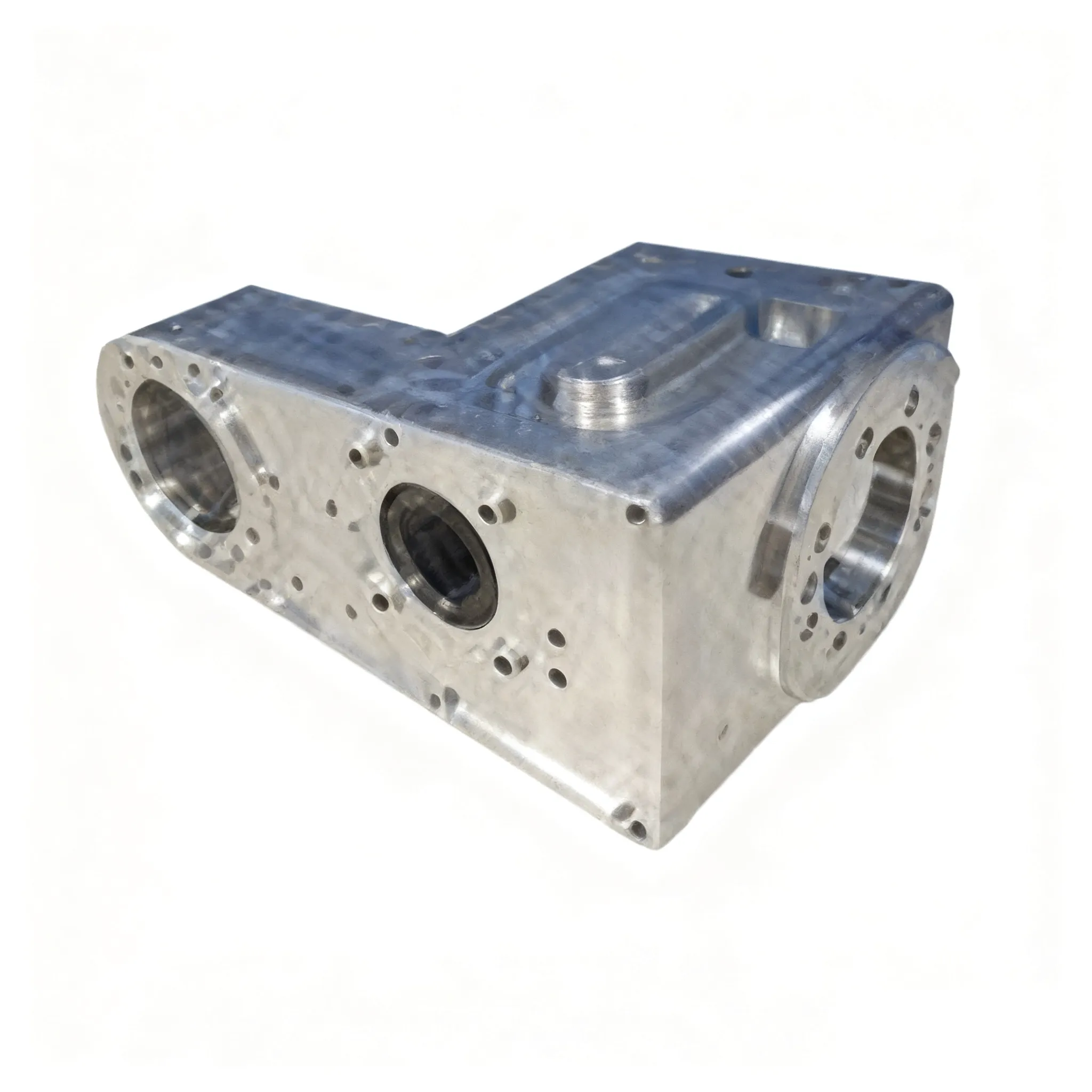
Key Tolerance Considerations for Robotic Joint Shells
The required tolerances vary based on the shell's specific function and mating components. Here are the primary categories:
-
Bore and Shaft Fits: These are paramount for bearing and axle seats. Common fits include:
-
Snug Fit (H7/g6): For precise bearing locations with easy assembly.
-
Interference Fit (H7/p6): For permanent bearing mounting without additional hardware.
-
-
Geometric Dimensioning and Tolerancing (GD&T): This is often more critical than linear dimensions for ensuring proper assembly and rotation.
-
True Position: Controls the location of bore patterns.
-
Concentricity/Cylindricity: Ensures bores are perfectly round and aligned to prevent wobble.
-
Parallelism/Perpendicularity: Guarantees mounting faces are square to rotation axes.
-
-
Surface Finish: A smooth internal finish (e.g., Ra 1.6 µm or better) reduces friction and wear on seals and moving parts.
The following table outlines typical tolerance ranges for a functional prototype shell:
| Feature | Typical Tolerance Range | Critical Reason |
|---|---|---|
| Bearing Seat Diameter | ±0.012 mm to +0.025/-0 mm | Ensures proper bearing press-fit or clearance |
| Mounting Hole Pattern | ±0.05 mm (True Position) | Allows for precise assembly to adjacent links |
| Face Flatness | 0.02 mm per 25 mm | Prevents distortion when fasteners are tightened |
| Critical Wall Thickness | ±0.1 mm | Maintains uniform strength and weight balance |
CNC Prototype Humanoid Robot Joint Support Shell FAQ
Q: What is the most common tolerance mistake in early joint shell prototypes?
A: The most common mistake is specifying tolerances that are too tight across the entire part. This unnecessarily increases cost and lead time. Applying precise tolerances only to critical interfaces, like bearing seats, while relaxing others for non-functional features is a key design-for-manufacturing skill we apply at WDF.
Q: How does material choice impact achievable tolerances in CNC machining?
A: Material stability directly impacts results. Metals like aluminum 6061 are ideal for CNC Prototype Humanoid Robot Joint Support Shell components as they machine predictably with excellent stability. Plastics like POM (Delrin) are dimensionally stable but may require adjustments for press-fits due to creep, while composites can be more challenging.
Q: Can you hold tight tolerances on large or complex-shaped joint shells?
A: Yes, but it requires expert planning. Multi-axis CNC machining and strategic sequencing of operations are essential to maintain accuracy across large parts. Our team at WDF utilizes advanced 5-axis equipment and in-process verification to ensure that even complex, organic-shaped shells meet their stringent geometric requirements.
Achieving the perfect balance of precision, performance, and prototype agility is our expertise. If your project demands a CNC Prototype Humanoid Robot Joint Support Shell built with the meticulous tolerance control necessary for true functional testing, partner with a team that understands the mechanics of motion.
Contact us today at WDF to discuss your project specifications and receive a detailed engineering analysis.