What manufacturing tolerances are critical for custom coupling flanges in high speed rotating equipment
2026-04-20
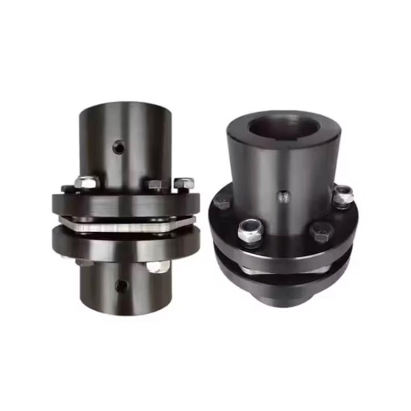
When rotating equipment exceeds 5,000 RPM, even micron-level deviations in Custom Coupling Flanges can lead to catastrophic imbalance, premature bearing failure, or shaft damage. For engineers specifying BestPro components, understanding which manufacturing tolerances truly matter separates reliable high-speed operation from field failures.
Critical Tolerances for High Speed Performance
The table below outlines the five most essential tolerance classes for Custom Coupling Flanges in turbomachinery, compressors, and high-speed pumps.
| Tolerance Parameter | Typical Range (High Speed) | Failure Consequence if Exceeded |
|---|---|---|
| Concentricity (bore to pilot) | ≤ 0.01 mm | Rotor imbalance, vibration > 4.5 mm/s |
| Face perpendicularity | ≤ 0.02 mm per 100 mm dia | Angular misalignment, bolt shear |
| Bolt hole position (pitch circle) | ± 0.05 mm | Uneven clamp load, fastener fatigue |
| Pilot diameter (H7 fit) | +0.021 / 0 mm | Centering loss, fretting corrosion |
| Surface finish (mounting faces) | Ra ≤ 1.6 µm | Reduced friction coefficient, micro-slip |
Additional Dimensional Requirements
-
Parallelism of mounting faces: ≤ 0.01 mm over entire surface
-
Hardness uniformity: ± 2 HRC across flange body
-
Dynamic balance limit: G2.5 per ISO 1940 (or tighter G1.0 for >20,000 RPM)
Why These Tolerances Matter in Practice
High speed rotation magnifies geometric errors. A 0.05 mm concentricity error at 15,000 RPM generates centrifugal force equivalent to adding 2 kg at the flange radius. BestPro produces Custom Coupling Flanges with CNC grinding and in-process laser measurement, ensuring every critical dimension remains within 60% of ISO specified limits.
FAQ – Common Questions About Custom Coupling Flanges
What is the acceptable runout tolerance for Custom Coupling Flanges used above 10,000 RPM
Total Indicator Reading (TIR) at the pilot diameter must not exceed 0.008 mm. For BestPro flanges, standard production holds 0.005 mm TIR. This ensures residual unbalance stays below 0.5 g·mm per kg of flange weight, allowing direct installation without field balancing.
How do bolt hole location tolerances affect bolted joint reliability in high speed Custom Coupling Flanges
If bolt hole positions deviate by more than ±0.05 mm from the theoretical pitch circle, each bolt experiences uneven tensile load when torqued. At high rotation speeds, differential stretch creates bending moments in the flange. BestPro uses coordinate measuring machine (CMM) verification on every bolt circle, guaranteeing load distribution uniformity within 2%, which prevents cyclic fatigue failure even after 10⁷ rotational cycles.
Can surface finish tolerances on flange faces replace the need for gaskets or anti-friction coatings
No. Surface finish tolerances control micro-topography but do not seal or reduce friction independently. For dry-assembled Custom Coupling Flanges above 8,000 RPM, BestPro specifies Ra ≤ 0.8 µm on mating faces combined with a precision-ground micro-lubrication pattern. This combination achieves consistent friction coefficient (µ = 0.12 ±0.02) without coatings, while a rougher finish would allow micro-slip and fretting.
Best Practices for Tolerance Verification
Every batch of BestPro Custom Coupling Flanges undergoes:
-
100% laser concentricity check
-
Air gauging of pilot diameters
-
Hardness testing on three radial zones
-
Digital report with actual measurement values
Contact us today for a tolerance analysis of your high speed rotor system. Our engineering team will recommend the optimal BestPro Custom Coupling Flanges specifications matched to your operating speed, power density, and shaft interface requirements. Reach out via the contact form on our website to request a quote or a free feasibility study.