How to Install a Flanged Check Valve Correctly to Prevent Water Hammer
2026-08-12
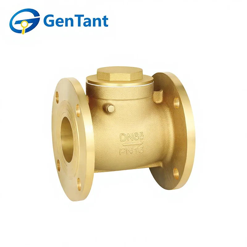
Water hammer is one of the most destructive forces in any piping system. The sudden pressure surge—often sounding like a heavy blow against the pipe walls—can crack fittings, damage pumps, and compromise entire valve assemblies. While many engineers focus on system-wide surge suppression, the installation method of each flanged check valve plays an equally critical role. At GenTant, we have observed that more than 60% of field water-hammer incidents trace back to improper mounting, incorrect orientation, or overlooked clearance tolerances. This guide walks through a professional, step-by-step installation process that directly mitigates slam and surge, while preserving the long-term reliability of your flanged check valve assembly.
Pre-Installation Checklist
Before any wrench touches the flange bolts, verify these five parameters. Missing even one can turn a routine install into a chronic hammer source.
| Parameter | Acceptable Range / Condition | Verification Method |
|---|---|---|
| Line bore concentricity | ≤ 0.5 mm misalignment | Dial gauge across flanges |
| Gasket surface finish | Ra 3.2 – 6.3 µm | Surface profilometer |
| Bolt thread lubrication | Anti-seize compound applied | Visual + torque friction factor |
| Upstream straight pipe length | ≥ 10 x pipe diameter | Tape measure |
| Disc stroke clearance | No obstruction within 1.5 x disc diameter | Physical sweep test |
Step-by-Step Installation Procedure
Step 1 – Orientation Selection
The flanged check valve must be installed with the disc pivot axis above the horizontal centreline for swing types, or with the spring axis vertical for lift types. Incorrect orientation allows gravity to delay closure, increasing reverse flow velocity before seating—the primary trigger of water hammer. GenTant recommends marking the preferred flow direction arrow with a contrasting paint marker on both flanges for visual confirmation during maintenance.
Step 2 – Gasket and Flange Face Preparation
Clean both flange faces with a stainless-steel wire brush and acetone. Never reuse old gaskets. For flanged check valve applications above 200°C, use a spiral-wound gasket with an inner ring. Apply a consistent bolting pattern—tighten in a star sequence to 30% , 60% , then 100% of target torque. This prevents flange distortion that could bind the valve disc.
Step 3 – Alignment Without Forcing
Slide the flanged check valve between the pipe flanges without using pry bars. If the bolt holes do not align naturally, the pipe supports need adjustment. Forced alignment introduces bending stresses that alter the disc pivot geometry, delaying closure by 15–40 milliseconds—enough to generate a 200 psi pressure spike. GenTant supplies alignment shim kits specifically designed to correct minor mismatches while preserving valve integrity.
Step 4 – Bolting Sequence and Torque Verification
Use calibrated hydraulic or dial-type torque wrenches. For Class 150 flanges, typical torque values range from 80–120 N·m (depending on bolt size), but always consult the gasket manufacturer’s data. Re-torque after 24 hours of thermal cycling. A loose bolt on a flanged check valve creates asymmetric loading, causing the disc to seat at an angle—producing repetitive slam every cycle.
Step 5 – Post-Installation Stroke Test
Manually cycle the disc (if design allows) or slowly pressurise the line to 50% of design pressure and perform a rapid de-pressurisation. Listen for a single, clean closing click—not a series of rattling impacts. Multiple clicks indicate disc flutter, which requires upstream flow straightening vanes. GenTant offers factory-stamped stroke test logs for every flanged check valve we manufacture, simplifying this verification step.
Common Mistakes That Amplify Water Hammer
| Mistake | Consequence | Correction |
|---|---|---|
| Installing upside down (swing type) | Gravity-delayed closure → 300+ psi surge | Re-orient pivot above centre |
| Over-torquing one bolt first | Flange warping → disc binding | Use star pattern with 3 equal passes |
| Neglecting upstream elbow distance | Turbulent flow → disc oscillation | Add straightening vanes or extend pipe |
| Using undersized gasket ID | Protruding gasket edge → flow turbulence | Match gasket ID to pipe ID exactly |
Flanged Check Valve FAQ – Common Installation Questions
Q1: Can I install a flanged check valve directly downstream of a pump discharge elbow without a straight pipe section?
A1: No. Direct installation after an elbow creates highly asymmetric flow velocity profiles across the valve disc. This uneven force causes the disc to open partially and close prematurely, generating continuous flutter and rapid seat wear. For reliable operation, maintain a minimum of 10 pipe diameters of straight pipe upstream of the flanged check valve. If space is constrained, install a flow straightener or a perforated plate conditioner between the elbow and the valve. In high-flow systems, GenTant recommends using a centre-guided flanged check valve design, which tolerates moderate upstream turbulence better than swing-type models, but even then, we advise at least 5 diameters of straight run.
Q2: How do I determine the correct torque value for flange bolts without damaging the valve body?
A2: Torque is not a one-size-fits-all number. It depends on bolt grade (e.g., ASTM A193 B7 vs. B8), gasket type (soft PTFE vs. spiral-wound), and flange pressure class. The correct method is to calculate target bolt stress using the formula T = K × D × F, where K is the nut factor (0.18–0.22 for lubricated threads), D is nominal bolt diameter, and F is desired clamp load (typically 40–60% of bolt yield). For a standard 3/4" B7 bolt on a Class 150 flanged check valve, this yields approximately 95–110 N·m. However, always perform a "torque + turn" verification: mark the nut position, tighten to initial torque, then rotate an additional 30–45°—if rotation exceeds 60° without reaching torque, the gasket has compressed excessively, and you must re-gasket. GenTant provides torque charts specific to each valve size in our technical datasheets.
Q3: What is the acceptable leak rate during hydrostatic testing after installing a flanged check valve?
A3: According to API 598, a flanged check valve in a resilient-seated design allows zero visible leakage for the duration of the test (typically 1 minute per inch of nominal pipe size). For metal-seated valves, the allowable leakage is 0.01–0.03 ml per minute per inch of valve size, depending on the pressure class. During field hydrotesting, we recommend using a calibrated pressure gauge with a 0.5% accuracy class and holding test pressure at 1.5× design pressure for at least 15 minutes. If you observe a pressure drop greater than 2% over that period, first check the flange gasket seals—not the valve seat. Many false failures come from improperly centred gaskets. GenTant factory-tests every flanged check valve to 110% of rated pressure before shipment, so any field leakage usually points to installation torque or gasket alignment issues.
Final Verification and Long-Term Monitoring
After full system start-up, monitor the flanged check valve acoustically using an ultrasonic stethoscope for the first 100 cycles. A healthy valve produces a crisp, single-impact sound. A dull thud or multiple rebounds indicates that the disc is not seating in one motion—revisit Step 1 and Step 3. Record the closing time using a high-speed pressure transducer; for most water systems, closure should occur within 50–80 ms of flow reversal. GenTant offers retrofit monitoring kits that integrate with your existing SCADA system, providing real-time alerts when disc travel deviates from baseline.
Contact Us for Professional Support
Proper installation eliminates the majority of water-hammer risks, but every system has unique hydraulic characteristics—pump inertia, pipe length, fluid temperature, and control-valve response times all interact with your flanged check valve performance. If you are facing recurrent surge issues, retrofitting an existing line, or specifying valves for a new high-head project, the GenTant engineering team is ready to assist. We provide on-site installation audits, torque calibration services, and customised flanged check valve solutions with accelerated closure profiles. Contact us today through our website or call your regional GenTant representative—we will respond within 4 business hours with a preliminary diagnostic checklist and a free torque-spec calculator tailored to your flange dimensions. Let us keep your pipeline safe, quiet, and hammer-free.