How Do You Install and Wire a 433MHz Safety Edge Sensor Processor Correctly
2026-10-22
Installing a 433MHz Safety Edge Sensor Processor correctly is critical for reliable obstacle detection, regulatory compliance, and long-term gate and door safety. Whether you are retrofitting an existing operator or commissioning a new automated system, FT designs its processors to simplify wiring, reduce interference, and deliver stable wireless performance in demanding environments. This guide walks through the practical steps professional installers follow, from pre-installation checks to final testing.
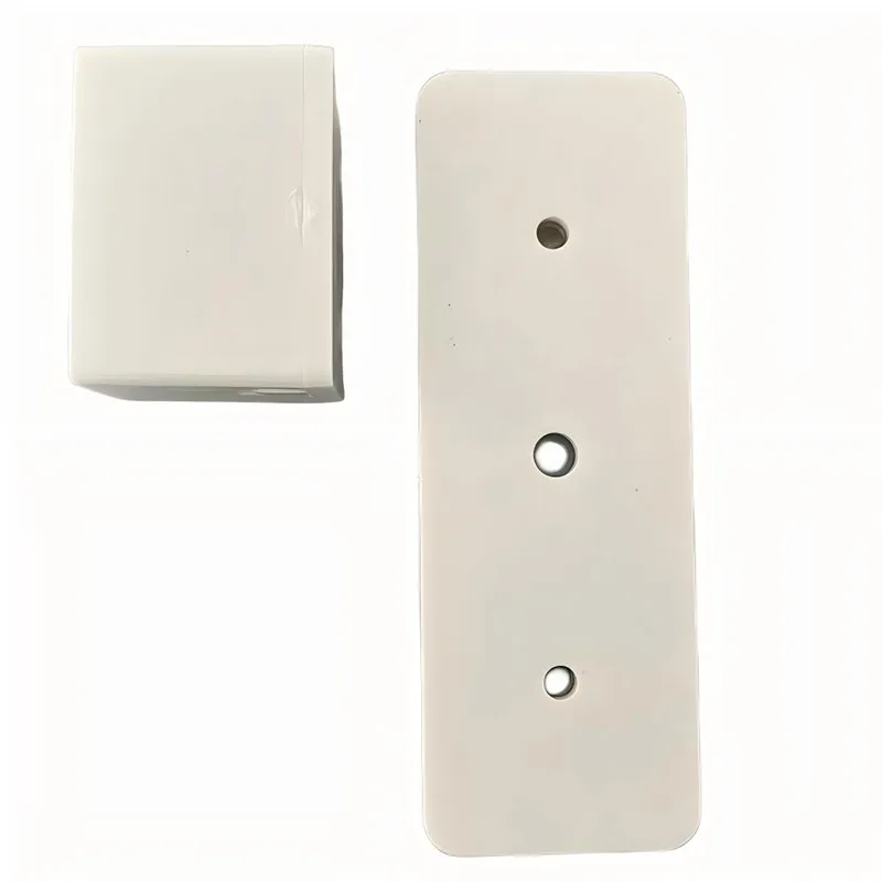
Pre-Installation Checklist
Before mounting anything, confirm the fundamentals. A missed detail here causes most commissioning failures later.
| Check Item | What to Verify | Why It Matters |
|---|---|---|
| Operating voltage | Confirm 12–24V AC/DC matches the FT processor rating | Prevents board damage |
| Safety edge type | 8.2kΩ resistive or optical, as supported by the model | Ensures correct signal decoding |
| Receiver pairing | Transmitter and 433MHz Safety Edge Sensor Processor are pre-paired or pairing mode is accessible | Avoids failed learn cycles |
| Cable routing | Keep antenna wire away from motor and mains cables | Reduces EMI and false triggers |
| Enclosure rating | IP54 or higher for outdoor gates | Protects against moisture ingress |
Step-by-Step Installation and Wiring
-
Isolate power. Disconnect mains supply and confirm zero voltage at the operator terminals before touching any wiring.
-
Mount the processor. Fix the FT unit inside the operator housing or a protected enclosure, keeping the antenna vertical and clear of metal surfaces.
-
Wire the power supply. Connect the supply to the designated terminals, observing polarity where marked.
-
Connect the safety edge. Terminate the resistive or optical edge leads to the sensor input terminals, keeping cable runs short and shielded where possible.
-
Wire the output to the operator. Connect the relay or open-collector output to the operator's safety input (typically the stop or reverse terminal), following the operator manufacturer's diagram.
-
Pair the transmitter. Enter pairing mode and trigger the safety edge to register the device.
-
Test and verify. Run the edge test, confirm the operator reverses on activation, and check signal strength at the furthest point of travel.
| Terminal | Function | Typical Connection |
|---|---|---|
| + / − | Power input | 12–24V AC/DC supply |
| SE1 / SE2 | Safety edge input | Resistive or optical edge |
| COM / NO | Relay output | Operator safety input |
| ANT | Antenna | Vertical, unobstructed |
Common Wiring Mistakes to Avoid
-
Running the antenna parallel to motor cables, which causes intermittent false activation.
-
Using unshielded cable on long safety edge runs, increasing noise pickup.
-
Skipping the edge test after pairing, leaving faults undetected until a real obstruction occurs.
-
Mounting the 433MHz Safety Edge Sensor Processor inside a sealed metal box, which severely attenuates 433MHz signals.
FAQ
Q: What range can I expect from a 433MHz Safety Edge Sensor Processor in a typical gate installation?
A: Most FT units achieve reliable line-of-sight ranges of 50–100 meters, though metal structures, walls, and motor noise reduce this significantly; always test at the furthest travel point and consider a repeater or repositioned antenna if signal strength is marginal.
Q: Can a 433MHz Safety Edge Sensor Processor be used with both resistive and optical safety edges?
A: It depends on the model, as some FT processors support 8.2kΩ resistive edges only while others accept both resistive and optical inputs; confirm the specification before ordering, and never connect an edge type the processor is not rated to decode, as this can cause permanent non-detection.
Q: How do I troubleshoot a 433MHz Safety Edge Sensor Processor that triggers randomly without an obstruction?
A: Random triggering usually points to electromagnetic interference or a weak signal, so check antenna placement away from motor cables, verify supply voltage stability, inspect edge wiring for moisture or damage, and re-pair the transmitter; if faults persist, test with a second paired device to isolate whether the processor or the edge is at fault.
Final Verification
Complete a full cycle test: activate the edge at slow and fast travel speeds, confirm the operator reverses within the required distance, and document the results. A correctly installed 433MHz Safety Edge Sensor Processor from FT should deliver consistent, repeatable detection with no false triggers.
Contact us today to discuss the right FT 433MHz Safety Edge Sensor Processor for your gate or door project, request a datasheet, or get installation support from our technical team.