How Can You Measure Rotor Balance Weight Field Adjustments Without a Full Balancing Machine
2026-07-06
Balancing a high-speed rotor is rarely a workshop luxury. When a turbine, compressor, or fan exhibits vibration on-site, the immediate question is not if the Rotor Balance Weight needs adjustment, but how to execute that adjustment accurately without a $200,000 balancing bunker. Field balancing is a science of methodical measurement, leveraging physics over hardware. At HAWEN, we have spent decades refining portable solutions that deliver workshop-grade precision on the factory floor. This guide outlines the proven measurement techniques, calculation frameworks, and practical safety nets for field adjustments of your Rotor Balance Weight system.
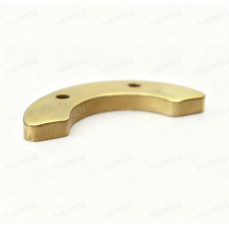
The Core Principle: Influence Coefficients Over Hard Bearings
Without a hard-bearing balancing machine, you cannot directly measure unbalance forces. Instead, you measure response—vibration amplitude and phase angle. The industry-standard approach is the Influence Coefficient Method. This involves attaching a trial Rotor Balance Weight of known mass and position, running the rotor to operating speed, and recording the vibration change. The difference between the baseline and trial run reveals the rotor’s sensitivity to weight at that specific plane. Field measurements rely on three critical tools:
-
Portable Vibration Analyzer (with FFT capability)
-
Key-Phase Sensor (optical or proximity probe) for phase reference
-
Precision Scale (0.1g resolution) for your Rotor Balance Weight pieces
Step-by-Step Measurement Protocol (Single-Plane Example)
| Step | Action | Measurement Output |
|---|---|---|
| 1 | Mount accelerometer at bearing housing (vertical/horizontal) | Baseline vibration amplitude (mil/s or mm/s) |
| 2 | Align key-phase sensor with rotor keyway | Phase angle reference (degrees) |
| 3 | Run rotor to normal operating speed (hold steady) | Record baseline vector O (amplitude + phase) |
| 4 | Stop rotor; attach trial Rotor Balance Weight (known mass) at 0° | Trial mass value (grams) |
| 5 | Restart rotor to same speed | Record trial vector O+T |
| 6 | Calculate influence coefficient C = (Trial Response – Baseline) / Trial Mass | Vector with units (amplitude/g, phase/g) |
| 7 | Compute required correction weight = – (Baseline / C) | Final correction mass and angle |
This field method yields an accuracy within ±15% of a shop balancer, which is sufficient for ISO 1940-1 Grade G2.5 or G1.0 rotors. HAWEN portable balancing kits include pre-calculated influence coefficient tables for common rotor geometries, reducing trial-run iterations from five to two.
The Critical Role of Phase Angle
Many field technicians obsess over weight mass but ignore phase. A 1‑gram error in phase angle of 10° reduces correction effectiveness by nearly 30%. To measure phase accurately without a full machine, you must:
-
Use a strobe light triggered by the key-phase pulse to "freeze" the rotor marking.
-
Mark the rotor surface with reflective tape at 0°; the analyzer computes phase lag automatically.
-
Always perform a "bump test" to confirm that your trial Rotor Balance Weight is not exciting a natural resonance – if amplitude doubles, abort and reduce trial mass.
Three Practical Measurement Alternatives (If No Analyzer)
| Method | Equipment | Accuracy | Best For |
|---|---|---|---|
| Stroboscopic visual | Strobe light + degree tape | ±20° | Low-speed (<3,000 RPM) overhung fans |
| Accelerometer + oscilloscope | Piezo sensor + scope with X-Y mode | ±10° | Mid-speed pumps with accessible shafts |
| Smartphone FFT apps (validation only) | MEMS accelerometer + Bluetooth | ±30° | Rough sorting; not for final trim |
For any critical asset, HAWEN strongly advises against methods #2 and #3 for final correction; they serve only as diagnostic cross-checks. The gold standard remains a dual-channel portable balancer that simultaneously measures two planes – but if you must choose one plane, always balance the plane with the highest vibration velocity.
Safety and Statistical Averaging
Field conditions are noisy. Ambient turbulence, thermal growth, and bearing oil film variations can skew a single measurement. To increase confidence:
-
Take three consecutive baseline runs; average the amplitude and phase.
-
Reject any run where speed fluctuates beyond ±2% of nominal.
-
Install the final Rotor Balance Weight in split halves (e.g., 50% correction at calculated angle, 50% 180° opposite) to allow fine-tuning without re-welding.
-
Perform a validation run – if residual vibration is below 0.5 mm/s (RMS), the field adjustment is successful.
Frequently Asked Questions (FAQ) About Rotor Balance Weight Field Measurement
Q1: How many trial runs are typically needed to determine the correct Rotor Balance Weight without a balancing machine?
A: With the influence coefficient method and a quality portable analyzer, you need exactly two runs – one baseline and one with a single trial weight. The third run is your verification (correction installed). If your rotor has significant nonlinearity (e.g., journal bearings with variable oil films), you may require a third trial at a different angular position to confirm the coefficient. In practice, HAWEN field engineers complete the entire procedure in three start-ups, provided the rotor speed is stable and the trial mass is between 5–15% of the estimated unbalance.
Q2: What is the maximum allowable residual vibration after a field Rotor Balance Weight adjustment, and how do I measure it without a full balancer?
A: The limit depends on your ISO 1940-1 balance quality grade. For a turbine at 10,000 RPM (G2.5), the allowable residual unbalance per plane is approximately 2.5 g·mm/kg. In field terms, this translates to a vibration velocity below 2.8 mm/s (RMS) for most industrial machinery. You measure this using the same portable accelerometer – after installing the correction weights, restart the rotor and record the steady-state amplitude. If the reading is below the ISO threshold and the phase angle remains consistent across three consecutive runs, your adjustment is validated. HAWEN portable balancers display this pass/fail criteria automatically, eliminating guesswork.
Q3: Can thermal expansion during operation alter my field-measured Rotor Balance Weight correction, and how do I account for it?
A: Absolutely. A rotor at ambient temperature (25°C) and one at 200°C have different shaft bow and modulus of elasticity. The correction weight calculated from a cold start may shift by up to 15% at full load. To compensate, perform your baseline and trial runs at normal operating temperature – let the machine run unloaded for 20–30 minutes until bearing temperatures stabilize. If that is unsafe, use the "cold-to-hot" correction factor provided in HAWEN material charts (typically +8% mass for steel rotors over 150°C delta). Always install the final Rotor Balance Weight on a thermally stable surface (not on thin shrouds) to minimize differential expansion errors.
Final Checklist Before You Cut Weight
-
Verify rotor speed is within ±1% during all measurement runs.
-
Confirm the trial Rotor Balance Weight is securely attached (tack-weld or screw-lock).
-
Document all phase angles relative to the fixed key-phase marker – never reset zero.
-
Calculate the correction mass twice (once manually, once via analyzer software) to catch arithmetic errors.
-
For overhung rotors, measure axial as well as radial vibration – unbalance here produces axial "wobble" that single-plane radial data misses.
Field balancing without a full machine is not a compromise; it is a disciplined exercise in vector mathematics and vibration physics. The tools are smaller, but the principles remain unyielding. Over the past 18 years, HAWEN has supplied over 600 portable balancing systems to power plants, refineries, and wind farms – each kit designed to turn a complex shop procedure into a safe, repeatable field routine. The key is not the machine you lack, but the measurement protocol you follow.
Contact Us – If your rotor is exhibiting unexplained vibration or you need a tailored field balancing procedure for your specific equipment, the HAWEN engineering team is ready to assist. We offer on-site support, rental portable balancers, and custom Rotor Balance Weight kits with pre-drilled blanks for rapid installation. Let us help you turn field measurements into permanent reliability – because every rotor deserves precision, even without the big machine.