Dosing System Services for Precision Chemical Feed and Process Control
2026-08-22
In the realm of industrial processing, precision isn't just a goal—it's the difference between consistent output and costly variability. Dosing system services for precision chemical feed and process control lie at the heart of this challenge, ensuring every drop of additive or reagent lands exactly where it should, when it should. But what separates a system that merely works from one that truly optimizes your operation? At Fanchang Machinery, we've spent years refining the answer—and the insights might surprise you.
Calibration Routines That Keep Dosing Pumps Within Tight Tolerances
Dosing pumps drift. Even the best units lose a fraction of a percent here, gain a few microliters there, until a process that once ran perfectly starts showing off-spec results. Calibration routines are what pull them back in line, and the ones worth keeping are built around regular, repeatable checks rather than firefighting after a bad batch.
A practical routine starts with a known volume and a stopwatch. Set the pump to its typical operating speed, catch the output in a graduated cylinder, and compare what you get against what the controller thinks it delivered. Do this at three points: low, mid, and high flow. The spread tells you more than any single reading, because a pump can be dead-on at 50% and still fall apart at 10%.
Once the baseline is set, tighten the loop with scheduled verification. For most chemical feed applications, a weekly gravimetric check using a laboratory balance will keep drift under 1%, which is enough for pH control or chlorine dosing. Pumps handling expensive or hazardous fluids may need daily checks, while simple water treatment can stretch to monthly. The key is writing down the correction factor and applying it consistently, not just noting that the pump was “close enough.”
Retrofitting Legacy Chemical Feed Systems Without Downtime
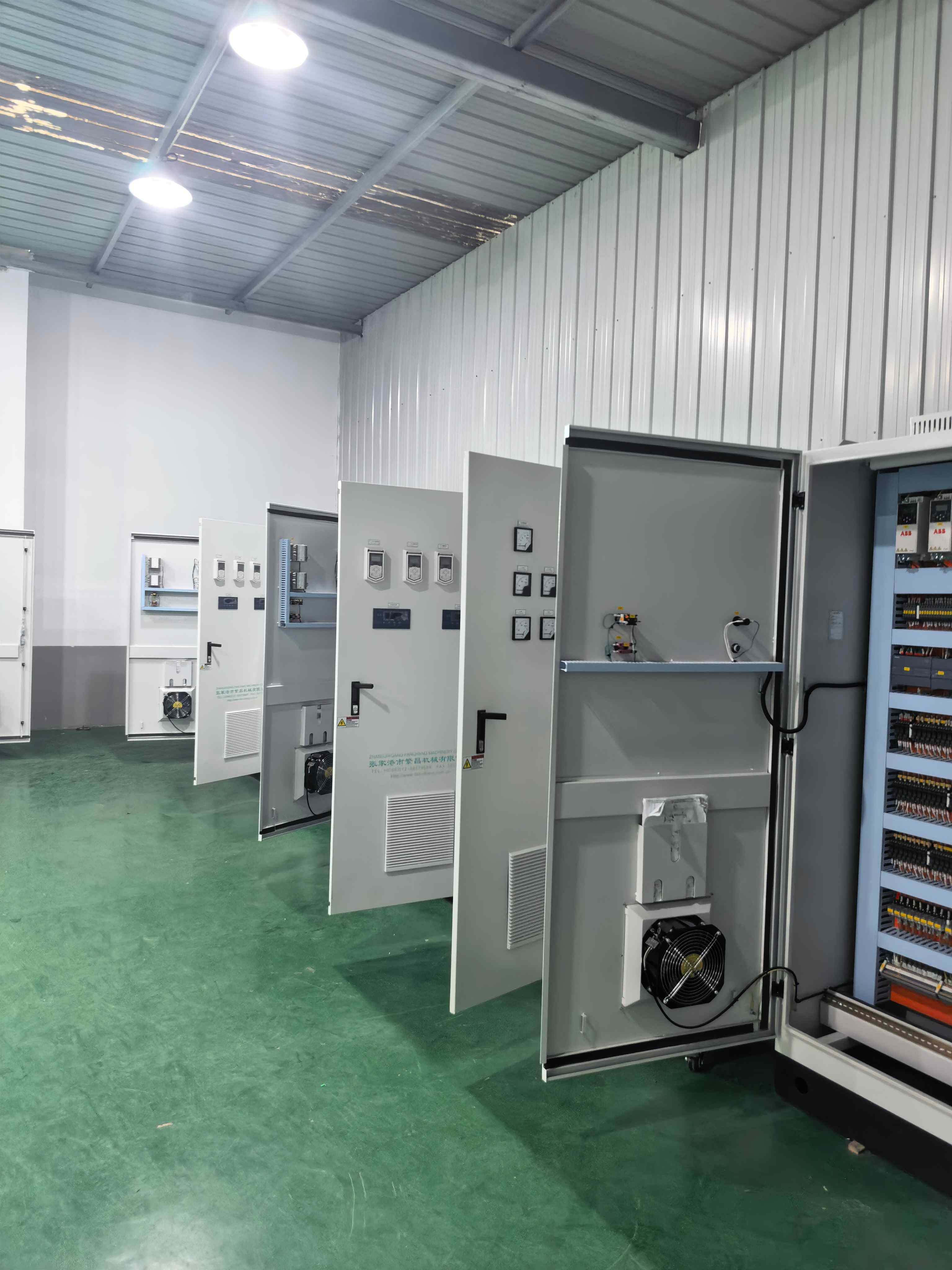
Upgrading an aging chemical feed setup often feels like deciding between shutting down critical processes or tolerating outdated dosing accuracy. But with careful staging, you can swap out worn pumps, replace brittle tubing, and integrate smarter controllers while the main line keeps running. The trick lies in building a temporary bypass loop, matching chemical compatibility exactly, and pressure-testing each new segment before cutting over. Operators on the floor appreciate this approach because it avoids the usual weekend scramble and keeps discharge permits safely within limits.
One overlooked detail is carrying out a live load bank test on the new feed skid before tying it into the existing manifold. Instead of relying on vendor spec sheets, run the replacement metering pump against a calibrated rotameter at three different stroke lengths while the legacy system still handles the daily demand. This gives you real turndown data under actual backpressure, revealing cavitation or loss of prime issues that only show up when the suction line is slightly starved. Once the numbers line up, a quick valve sequence transfers flow without a single missed dose.
Documentation also deserves a fresh look. Rather than creating another static manual, have the commissioning team film the cutover using a head-mounted camera, then link those clips to the new P&ID updates in the CMMS. That way, the next engineer who has to troubleshoot at 2 a.m. can watch exactly how the temporary crossover was valved and why the check valve was oriented the way it was. It’s a small habit, but it turns a risky retrofit into a teachable moment for the whole maintenance crew.
Matching Pump Output to Real-Time Process Flow Signals
A pump running at a fixed speed rarely matches what the process actually needs at any given moment. Flow demands shift with valve positions, heat exchanger loads, and batch schedules, yet the pump keeps pushing the same volume. The result is either excess pressure throttled away across control valves or intermittent starvation downstream. Tying pump speed to real-time flow signals turns the pump into a responsive element instead of a constant-force device.
The control loop reads the flow transmitter's signal, compares it to the desired setpoint, and adjusts the drive frequency accordingly. This is not a simple on-off response; the tuning has to account for inertia in the piping and the pump's own curve. A well-tuned loop nudges the speed up or down in small, continuous corrections rather than waiting for a large error to develop. That keeps discharge pressure stable without hammering the motor or causing cavitation at low flow conditions.
What often gets overlooked is the need to filter the flow signal before it reaches the controller. A raw signal with noise from turbulence or sensor placement can make the pump hunt, wasting energy and wearing out seals. A short damping time or a moving average filter removes the spikes while preserving the true trend. Once that clean signal drives the pump, energy consumption drops, valve wear decreases, and the process stays on target with far less operator intervention.
Chemical Compatibility Checks That Prevent Premature Seal Failure
Seal materials degrade fastest when the elastomer and the process fluid aren't matched at the molecular level. A nitrile lip seal might hold up fine in mineral oil, yet the same compound can swell, crack, or turn gummy within days when exposed to ester-based hydraulic fluids or aggressive cleaning solvents. Swelling changes the lip's interference and contact pressure, while shrinkage opens leak paths or lets the seal spin in the housing. Neither failure mode shows up in a standard hardness check until the damage is already done.
Running a structured compatibility screen early in the design phase does more than verify the base polymer. Fillers, plasticizers, and cure systems often react before the backbone does, so a compound that passes a generic “oil resistant” rating can still fail when a specific additive or trace contaminant is present. The most useful tests combine long-term immersion in the actual service fluid at the upper operating temperature with periodic measurement of volume change, tensile strength, and compression set. A volume change beyond roughly ±10–15% or a sharp drop in elongation signals that the seal will not hold its geometry under load.
Chemical compatibility also needs to account for mixed exposures. A seal that tolerates each individual chemical may break down rapidly when cleaners, rust inhibitors, or process byproducts combine in the sump or splash zone. Checking only the primary fluid misses these secondary contacts. Short-listing candidates through a compatibility table is a reasonable first filter, but final validation should always use immersion coupons or bench tests under conditions that mirror the real seal environment, including temperature cycling and intermittent wetting. The goal is not to find a material that survives forever, but to define a safe operating envelope where swelling, hardening, and extraction remain low enough to preserve the seal's lip force and contact width through the expected service interval.
Tuning PID Loops for Stable Residual Control
Residual control loops tend to misbehave when the integral term is tuned as if the process responds quickly. Most residual loops involve a lag between a valve or damper adjustment and the measured leftover pressure, flow, or temperature. Start by recording a small open-loop step response to get the dead time and the main time constant. If the dead time is more than about a quarter of the time constant, keep the proportional gain modest and set the integral time to at least twice the dead time. Avoid adding derivative unless the signal is clean, because derivative on a noisy residual measurement will amplify jitter and make the output hunt.
Integral windup is another common reason residual control becomes unstable. When the actuator hits a physical limit, a standard PI controller keeps integrating the error and then overcorrects once the limit clears. Use anti-windup logic that freezes or backs off the integral term based on the actual actuator position, not just the controller output. A common fix is to feed the real output back into the integral calculation so the integral state tracks the saturated value. This keeps the reset action from piling up during long disturbances and gives a smoother return to the residual setpoint.
After the initial settings, tune by making small setpoint changes in both directions and watching the shape of the response. If the residual overshoots and then oscillates with a period close to the process dead time, reduce the gain by 10 to 20 percent before touching the integral. If the residual settles too slowly with no overshoot, increase the integral action in small steps rather than raising the gain. For lag-dominant residual loops, a gain reduction plus a slightly longer integral time often produces a stable, slightly overdamped response that rejects load changes without continuous cycling.
Maintenance Logs That Simplify Regulatory Inspections
A well-kept maintenance log does more than record work orders; it creates a clear, chronological trail that inspectors can follow without asking repeated questions. When every entry includes the date, the equipment involved, the specific action taken, and the technician's signature, the log becomes a document that answers most compliance questions before they're raised.
Instead of scrambling to piece together scattered notes or outdated spreadsheets, facility teams can point inspectors to a single, organized source. For example, a quarterly fire pump test entry that shows the baseline pressure, the observed pressure, and any follow-up adjustment lets an inspector verify the asset's status in seconds. Grouping entries by asset type or location, flagging overdue items, and attaching relevant photos or calibration certificates turns the log into a working file that mirrors the structure of many inspection checklists.
Regular review of the log also prevents small gaps from becoming findings. When supervisors routinely check for missing signatures, unclear descriptions, or incomplete follow-up actions, the log stays inspection-ready at all times. This habit shortens the actual inspection visit and builds trust with regulators, who can see that maintenance is treated as a controlled, consistent process rather than an afterthought.
FAQ
We regularly work with aggressive acids, caustics, polymers, and slurries. The key is matching wetted materials and pump head geometry to the fluid’s viscosity and reactivity, so the system stays reliable without constant manual intervention.
Rather than relying on fixed stroke settings, we use closed-loop control tied to flow meters, pH probes, or turbidity sensors. The controller adjusts pump speed or stroke length in real time, which keeps dosage on target even when upstream flow or water quality shifts.
We handle the full scope—skid fabrication, piping, electrical, and commissioning. Having one team responsible for the whole package prevents finger-pointing and makes startup much faster, especially on retrofit projects with limited space.
We set up condition-based maintenance schedules that monitor check valve wear, diaphragm fatigue, and calibration drift. Instead of fixing things after they fail, you get early warnings and scheduled service windows that don’t interrupt production.
Yes, we integrate via 4-20 mA, Modbus, Profibus, or Ethernet/IP. We’ll map the dosing parameters into your PLC or SCADA so operators see chemical usage and alarms on the same screens they already use, without a separate interface.
We design the suction and discharge lines with proper slope, use degassing valves where needed, and select pump heads that tolerate vapor bubbles instead of locking up. This is especially important for sodium hypochlorite and hydrogen peroxide applications.
We focus on the whole hydraulic path from day tank to injection point, not just the pump. That includes line sizing, pulsation dampening, back pressure valves, and injection quills, which many suppliers leave to the contractor. The result is smoother chemical delivery and less maintenance.
Conclusion
Precision chemical feed depends on more than selecting the right pump; it requires ongoing calibration that keeps stroke length and speed within tight tolerances. Our service technicians run multi-point verification routines against certified references, adjusting eccentric settings and diaphragm tension so that each dose matches the intended setpoint. When older systems need upgrading, we retrofit legacy panels and pumps without interrupting production—hot-swapping control modules and re-terminating signal wiring during scheduled slow windows. The real payoff comes from linking pump output to live process flow signals. Instead of fixed-speed operation, the feed rate tracks flowmeter pulses or 4–20 mA inputs, compensating for demand swings and preventing under- or over-feed even when plant throughput changes.
Chemical compatibility is often the root cause of premature seal and diaphragm failure, so we verify wetted materials against the exact product formulation, concentration, and temperature before commissioning. That check extends to O-rings, check valves, and injection quills. Once the pump is running, we tune PID loops for stable residual control by adjusting gain, integral, and derivative parameters against actual basin or line response—not just factory defaults. This reduces oscillation around the chlorine or polymer setpoint and cuts chemical waste. Finally, our maintenance logs capture every calibration, repair, and part swap in a format that auditors can follow. Each entry ties to a pump ID, time stamp, and reason code, which simplifies regulatory inspections and trend analysis for long-term reliability.
Contact Us
Contact Person: Darye WANG
Email: [email protected]
Tel/WhatsApp: 86-13501017897
Website: https://www.fcntd.com/